
This is the Sister Post to ‘Electrical Basics’ Read that one first!!
What the curriculum thinks you need to know:
PC_BK_41 Capacitance, inductance
PC_BK_42 (Resistors and) Wheatstone bridge: principles, uses
PC_BK_46 Circuit breakers, fuses
PC_BK_47 Transformers, inductance
PC_BK_48 Transistors, diodes
PC_BK_49 Amplifiers: band width, low pass, high pass, band pass filters
PC_BK_53 Piezo-electric devices
PC_BK_56 Transducers and strain gauges
PC_BK_64 Pressure transducers
Ok, that’s quite a list… Lets get going.
What you need to know (The theory):
Capacitance and Inductance
Have a look at the post on defibrillators, this goes into the details of these two components (e.g. Capacitors and Inductors)
Resistors
A resistor is an electrical component which works to reduce current flow by adding resistance to an electrical circuit.
Resistors are made up of thin metal wire which is sometimes coiled. The thinner the wire and the longer the piece of wire, the higher the resistance. The wires are coiled to make them more compact.
If we look at ohms law, we see the following:
V = I x R
(V = Voltage; I = Current; R= Resistance)
Then if we rearrange this:
I = V/R
Hence if we increase the resistance, the flow of current will decrease. So if we want to maintain the same flow, we need to increase the driving voltage to compensate.
These are used to decrease current flow (think adjusting volume in an amplifier) and also controlling voltage (see wheatstone bridges below…)
Wheatstone Bridges
The college have an inbuilt love for the Wheatstone bridge. Its a concept that confuses many people, so I’ll try to simplify it whilst keeping it accurate.
So what is a wheatstone bridge?
Most strain gauges and pressure transducers (see below!) produce a resistance. Now resistance is very difficult to measure whilst the component is in a circuit. This is because the other components in the circuit will alter the measured resistance and make your measurement inaccurate. Also if you’ve ever used a multimeter or similar to measure a resistor, they’re pretty slow to respond to changes in resistance. Not ideal for a monitoring circuit.
A Wheatstone bridge aims to turn the variable resistance of the strain gauge/pressure transducer into a variable voltage. This is then much easier to measure and turn into your readout you see on your screen.
How does it work?
If we put a resistor in a circuit, there will be a voltage drop across the resistor. Much like the pressure drop seen across a restriction/narrowing in a tube with a fluid flowing through it.
I’m going to introduce a different way of drawing circuits here as it makes it easier to understand. You can draw two horizontal lines, each of which is the same as either terminal of a battery/power source. These are then usually labelled with their respective voltages.

Basic electrical circuit.
If we put two resistors in series, there will be a sequential drop in voltage across these resistors. At point A, the voltage will be the supply voltage (+9v in this case). At point C, the voltage will be 0v. Point B however depends of the value (number of ohms) of each of the resistors. If both resistors are the same value (e.g. 100 Ohms), then the voltage at point B will be exactly half the difference between points A and C (in this case 4.5v).

Voltage Divider.
This is called a voltage divider. Its commonly used in electrical circuits to produce different voltages than your power supply is giving you.
Now if we change the value of resistor one you can change the voltage at point B. If resistor one reduces below resistor two then the voltage will be higher than 4.5v, if resistor one has a higher resistance than number two, then the voltage at point B will be lower than 4.5v. Remember it this way, more resistance leads to more voltage drop.
The voltage drop across each resistor works as a ratio to the relative resistance in each resistor. For instance, if we have resistor one at 200 ohms and resistor two at 100 ohms, then the ratio is 2:1. Hence the voltage drop across the resistors will be 2:1 (e.g. 6v across the first resistor and 3v across the second resistor). Remember the total must equal the difference between the two terminals of your power source (in this case 9v as in a 9v battery).
Yes, Yes great. What does this have to do with a Wheatstone bridge??
A Wheatstone bridge is basically two voltage dividers in parallel. If we put two voltage dividers next to each other, and make all the resistors the same value, the voltage between points B and E will be 0v. Because there is no difference between the voltages at these points.
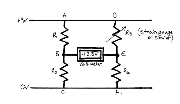
A Wheatstone Bridge
If we then change one of the resistors for our transducer, then we make what you see in monitoring circuits. As that transducer produces a different resistance (e.g. due to higher or lower pressure in a arterial line transducer), then the voltage between points B and E will change. We can then calibrate this voltage change against the pressure change and continuously measure changes in pressure. These will be read by your monitoring equipment as a voltage change which is nice and easy for a computer to display graphically or numerically for you.
Fuses & Circuit breakers
Fuses and circuit breakers are devices which stop current flow when the current flow exceeds a given level. They’re designed to protect electrical equipment and stop people getting electrocuted!
Fuses are simple. They are thin piece of wire which heats when the current level increases (as current flows in any conductor it heats up, but isn’t usually noticeable to touch). When the current heats the wire to a high enough level, it melts. This breaks the circuit and stops current flow. The smaller the value of the fuse (e.g. 1 amp vs. 13 amp) the thinner the wire in the fuse (assuming they are made of the same material that is).
The problem with a fuse is it breaks every time it ‘trips’. This is very annoying and can be a bit difficult to change in the dark when you can’t find a torch! So the solution is a circuit breaker. These work in various ways depending on the current level flowing through the breaker and in what circumstance they are used. In general though they work as a switch with an electromagnet next to it. As the current level increases over a certain point (each breaker is calibrated for a certain current flow) the electromagnet charges and pulls one terminal of the switch away, breaking the circuit. These are useful as you just ‘throw’ the switch and it can be reset and used again.
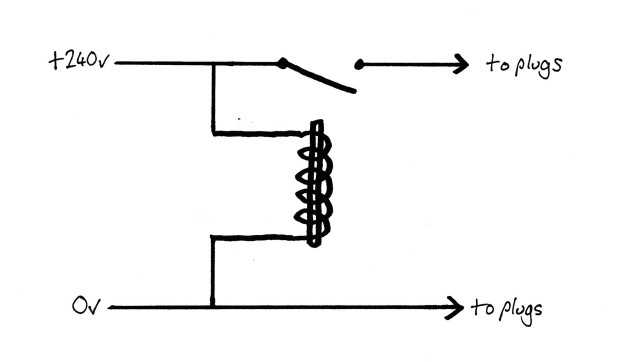
A Basic Circuit Breaker
Transformers
Mains voltage in the UK is 240v AC. So how do we get a different voltage? say the 5v DC your mobile needs to charge, or the ~5000V DC that defibrillator outside your theatre needs to work?
This is where transformers come in.
‘A transformer is a device which transfers electrical energy from one circuit to another through electromagnetic induction’
A transformer is made of two coils of wire (sometimes with an iron core). As we know from this post, passing current through a wire will induce an magnetic field. We also know when we put another wire into this magnetic field, an electric current is induced.
Voila! Electric current going from one wire to another without them touching. Its like magic.
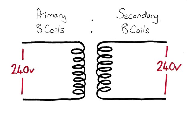
A Basic Transformer
If the coils have the same number of turns on them, then the induced current in the second coil will be at the same voltage as the first coil. Is we change the relative number of coils in the first and second (properly called the primary and secondary) coils, then the resultant voltage in the secondary coil changes. If the secondary coil has half the number of turns, the voltage is half that of the primary. If the secondary coil has twice the number of turns, the voltage is twice that of the primary. Hence we can induce higher or lower voltages than the mains supply voltage. This is termed a ‘step up’ or ‘step down’ transformer. Anyone who has ever imported a games console from japan in the past will know all about this.

Example of a ‘step down’ transformer
Another thing that is quite common is having ‘taps’ on the transformer. This is a wire coming out (usually half way!) along the secondary coil, allowing us to have two different voltages from one supply voltage.
Because the two sides of a transformer can be completely independent without any physical connection, they can be used to ‘isolate’ a circuit. In practical terms this just means that the second coil isn’t in contact with ground, so you can’t get shocked from it. It can also be used to stop sources of electrical noise, lots of types of audio equipment use a transformer for this purpose.
This is a good time to mention rectifiers. I wouldn’t learn too much about these except that they are used to turn AC into DC.
Your phone power adapter is basically just transformer with a rectifier (plus a few other bits and bobs to stop current surges etc) to turn mains 240v AC into the 5v DC your phone needs to charge.
The college also mentions inductance in the curriculum. See here for more on this.
Diodes and Transistors
Diodes are electrical components that allow current to flow in one direction only.

A Diode.
This is easy to remember if you look at the symbol. From one side there is a triangle ‘pointing’ the current through the ‘wall’. When current moves in this direction (left to right in the diagram) then it passes through the diode just fine. But in the opposite direction, the current hits the ‘wall’ and is stopped.
Transistors are components which open and close to allow movement of electrical current in response to a control voltage.

A Basic Transistor
Transistors can be thought of as electrical gates. They can get a bit confusing because of the various types and subtypes. They have three terminals. Two (the collector and emitter) comprise the route which current takes through the transistor, whilst the third (the base) is the ‘gate’ which I mentioned earlier. When current is applied to this third terminal the transistor opens and allows current to flow between the collector ans emitter.
Note 1: Current only flows when a control voltage is applied to the base. As soon as this stops, the flow of current between the collector and emitter stops. Think of this as needing to keep your finger on the switch to keep it working. Compare this with a thyristor which is the same idea but works in a latching fashion staying activated after the control voltage is removed and needing to be ‘reset’ to switch it off.
Note 2: The terms used here are for typical bipolar transistors. Other types use different terms (e.g a field effect transistor (FET) calls the terminals the anode, cathode and gate – perhaps easier to remember, but not as common).
Amplifiers
Most biological potentials are low amplitude electrical currents. The problem with these are they there doesn’t need to be an awful amount of noise before your signal is lost. Also your equipment needs to be very very sensitive to detect the signal.
An amplifier is a device which increases the amplitude of an electrical current/signal using a power supply
So we can increase the amplitude of these biological signals using an amplifier:

A Basic Amplifier
Note that the ‘gain’ of an amplifier refers to how much the amplitude increases. A gain of 2 doubles the amplitude of the initial signal.
As well as amplifying the ‘wanted’ signal, amplifiers will amplify any noise present at their input. The signal to noise ratio is the ratio of the amplitude of the signal you want, to the noise (or stuff you don’t want).
Pieces of equipment with a higher signal to noise ratio gives you more signal and less noise. Its worth noting that the way an amplifier works also introduces some noise into the signal itself. Higher quality amplifiers cause less noise to be produced (and hence better signal:noise ratio) but as a downside tend to be rather expensive. Just think of an expensive hifi vs a cheap boom box, one sounds awesome, one hissy and horrible.
One little point that gets asked about in regards to amplification and noise is common mode rejection. This is commonly used to remove electrical noise from circuits. There are types of amplifiers called ‘differential amplifiers’. Now these have two inputs and one output (typically!!). The inputs are usually labelled + and – on a circuit diagram.
The amplifier will amplify whatever the difference between the two inputs is. In practice, this means that any signal which is the same between the two inputs is cancelled out. So for instance if we have a signal with a bit of electrical noise from a power supply on input one, then we simply connect the power supply to input two, the amplifier will cancel out that power supply noise as its present on both inputs. as our ‘wanted’ signal is only on one input, it is amplified.

Differential amplifier; Here used to cancel out a signal.
Piezo-electric devices
This is covered in the post on ultrasound.
Transducers
Transducers are devices which change one type of energy into another type of energy.
Typically used transducers would be something like an arterial line pressure transducer (pressure into electrical energy) or a temperature probe (thermal energy into electrical energy).
Pressure transducers/strain gauges tend to work on the principle of an increasing pressure distorting/stretching a metal element or wire. This then changes the resistance of the wire. This wire can then be connected into a wheatstone bridge to produce a voltage in response to the pressure change. See the Pressure and its measurement post for more.
Temperature probes work in a few ways depending on the exact type, See this post for more on them.
Random Exam factoids (i.e. the things the college like asking):
- Remember your definitions of what each component does!
© Sam Beckett and Physics4FRCA, 2017. Unauthorized use and/or duplication of this material without express and written permission from this site’s author and/or owner is strictly prohibited.

Nice post, you’ve laid it out in a way that’s easy to understand. Great blog overall, keep up the good work.
LikeLike
Thanks this was a very good explanation of the Wheatstone bridge. Not laying out in a diamond and instead as two parallel voltage dividers is much more accessible
LikeLike