
What the curriculum thinks you need to know:
PC_BK_30 Measurement of volume and flow in gases and liquids, including pneumotachograph and other respirometers
I Recommend you read part one of this post first, or some of this may not make much sense!
Think where you need to know what the flow rates of gas are in an anaesthetic machine. Broadly, there are two places:
- The Gas flow into the machine (your fresh gas flow or FGF)
- Your gas flow into the patient (your inspiratory and expiratory flow)
What you need to know (The theory):
Flowmeters/Rotameters

Good ol’ fashioned Flowmeters on an anaesthetic machine
Flowmeters used to be common on anaesthetic machines but are systematically being removed! If you haven’t used a machine with one, find an old machine and have a play. They are used to measure the FGF into the machine. They also tend to be present on the auxillary oxygen supply of most machines, as they don’t require an electrical supply so are functional during an electricity blackout.
Flowmeters are classed as variable orifice and consist of a needle valve which controls the flow of gas through the flow meter and a tube which gradually increases in diameter. Inside the tube there is a bobbin.
As the gas flow increases, the number of molecules hitting the bobbin increases and hence the bobbin rises as the force acting on the bobbin from the flow of gas is more than that of gravity. As the bobbin rises up the tube, the gap around the bobbin increases which allows more and more gas to flow around it. Because density of gas will affect how much a bobbin rises, each flowmeter is calibrated for a specific gas.

Flowmeter/Rotameters are used to measure your fresh gas flow rates.
The college occasionally like asking about the bobbins themselves. All you need to know is that there are two main shapes, spheres and flutes. The spheres are round (obviously), so we read the level off the centre of the bobbin, whilst the conical are shaped more like a beaker, with a flat top. So the flow rate on these is read off the top of the bobbin. There are a few design perks to stop these bobbins sticking within the flowmeter. Spherical bobbins have a small surface area which comes into contact with the wall of the flowmeter so are unlikely to get stuck on it. The conical bobbins have flutes along their length which cause the bobbin to rotate on its long axis when gas flows. This helps stop them sticking.
Pneumotachograph

A Pneumotachograph – You’ll find these in most modern anaesthetic machines somewhere!
The pneumotachograph consists of a small wide tube with a mesh in it. The tube is widened to reduce the velocity of the flow of gas which helps maintain laminar flow (Reynold’s equation – see Gas Flow 1 – Theory). The mesh provides a small resistance. Ohm’s law says this increase in resistance must cause a pressure drop across the mesh to maintain flow.
From Ohm’s law (see part one again!), we can see that the pressure difference is proportional to the flow across the pneumotachograph. Or, as the flow increases the pressure drop across the resistance increases.
The pressure drop is measured by a differential pressure transducer across the resistance and flow rates can be worked out from the pressure difference.
Note that pneumotachographs also have the advantage of being bi-directional! All that happens is that when the flow reverses, the pressure change reverses. This is handy for measuring your inspiratory flow and expiratory flow rates.
Wright Respirometer
Another college classic is the Wright respirometer. Now I doubt you’ve ever actually seen one of these outside a museum setting. These work on the principle of a set of vanes which have a very low resistance to rotation. The flow of gas over these vanes makes them spin.

The Wright Respirometer
The amount of spinning is then proportional to the flow rate (and hence volume). These are great in that they are truly mechanical devices and need no power (like the rotameter), But have a number of disadvantages.
These include:
- Unidirectional – Can only measure flow in one direction (normally expiratory)
- Inertia – They tend to overestimate flow due to the continued spinning after flow has stopped due to inertia. This is an inevitable sideeffect of their low resistance to spinning (think low rolling resistance tyres affecting your stopping distance in your car).
Wright peak flow meter

The Wright Peak Flow Meter.
We’ve all used one of these things to measure an asthmatic patient’s peak flow. They work on the principle of a variable orifice (that slit down the side of the meter). As air is blown into the end of the meter it pushes the diaphragm down the meter. As the diaphragm moves, it opens a larger orifice for air to escape which lowers the attainable pressure of the gas expelled from the patient. Eventually the diaphragm cannot be moved any more and its position along the meter is proportional to the peak expiratory flow rate of the patient.
Pitot tubes

Pitot Tube on a Ferrari Formula 1 Car
Pitot tube on a F16 Fighter jet
Have you ever wondered what those things sticking out of airplanes and formula one cars are? They’re called ‘Pitot tubes’ (after Henri Pitot, a French engineer).
Think of a small tube with its opening facing forward and imagine someone running forward with that tube. Gas is forced down the tube as the tube ‘catches’ the molecules. Its the same thing as sticking your head out of car window with your mouth open. The faster you go, the more gas enters the tube or your mouth. Now, as more gas enters that tube the higher the pressure is within that tube. So we can say that the pressure in the tube is proportional to the speed at which we are travelling. This is how planes tell how fast they are travelling.
In an airplane this is calibrated against atmospheric pressure (as obviously planes travel at different altitudes, and hence atmospheric pressure changes) with another tube facing out the side of the plane. A differential pressure transducer allows this data to be put into a computer. This is required as the lower the atmospheric pressure, the lower the number of molecules per unit area, so there will be a lower increase in pressure with increase in velocity (although proportionally the same just to confuse matters).

Example of a Pitot Tube in an aircraft.
So how can we use this to measure gas flow?
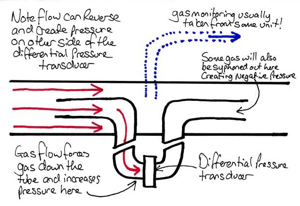
Pitot Tubes in an anaesthetic circuit
There is nothing to say the pitot tube has to be the thing moving! If we keep it still and use a setup as Above, any gas moving from left to right (or visa versa) will induce a pressure difference between the two tubes. This difference will be proportional to the Velocity of gas flow. Then by knowing the cross sectional area of the tube the gas is going through, we can work out the flow rate. You probably won’t see these in practice in the UK these days unless you work somewhere that uses ‘old school’ circuits routinely (Bain circuits and the like) as most flow analysis is done in the machines these days. If you do come across one, they have connections like the one below close to the patient and have three tubes coming from them, two for the Pitot tubes and one for the gas sampling tube.

Example of a connector with Pitot tubes in.
What you need to know (How it works in practice):
Remember all these devices measure a flow RATE. They don’t directly measure things like tidal volume. So they will usually give a reading in L/Min. Variables like tidal volume etc can be easily worked out by multiplying the flow rate by the inspiratory/expiratory time (in minutes!).
Things to remember with all gas flow monitoring systems is that they need to be calibrated for the gas mixture present. If this mixture changes (e.g. adding in helium into the mix), then the readings may be inaccurate. The degree of inaccuracy depends on the method of analysis used. Most modern machines will compensate for this with analysis of the content of the gas flow. Just be aware that some agents may cause havoc (Helium!).
Random Exam factoids (i.e. the things the college like asking):
- The college have asked previously about the order of flowmeters in an anaesthetic machine (e.g. which gas should come in first, middle and last). The answer they are looking for is that oxygen should be added last to minimise the chances of hypoxic mixtures being supplied when there is a leak in the flowmeters. Note this can be confusing as the oxygen is often on the left hand side so it would be logical it would be added first if we think the gas is moving left to right from flowmeters to vapourisers. However actually, its the other way around!
© Sam Beckett and Physics4FRCA, 2017. Unauthorized use and/or duplication of this material without express and written permission from this site’s author and/or owner is strictly prohibited.

Very helpful, thank you Sam. I am just on my way to be an examiner in a mock OSCE, and this was an excellent refresher!
LikeLike
great site and great article. I couldn’t find the flow 1 article though
LikeLike
It’s here: https://physics4frca.com/2017/11/16/gas-flow-1-theory/
LikeLike